Transparent nozzles manufactured to match the hole inlet radius and diameter of the Engine Combustion Network Spray D nozzle were mounted to a modified version of a common-rail Spray A injector body and needle. The mounting of the nozzle to the metal injector body is illustrated below.
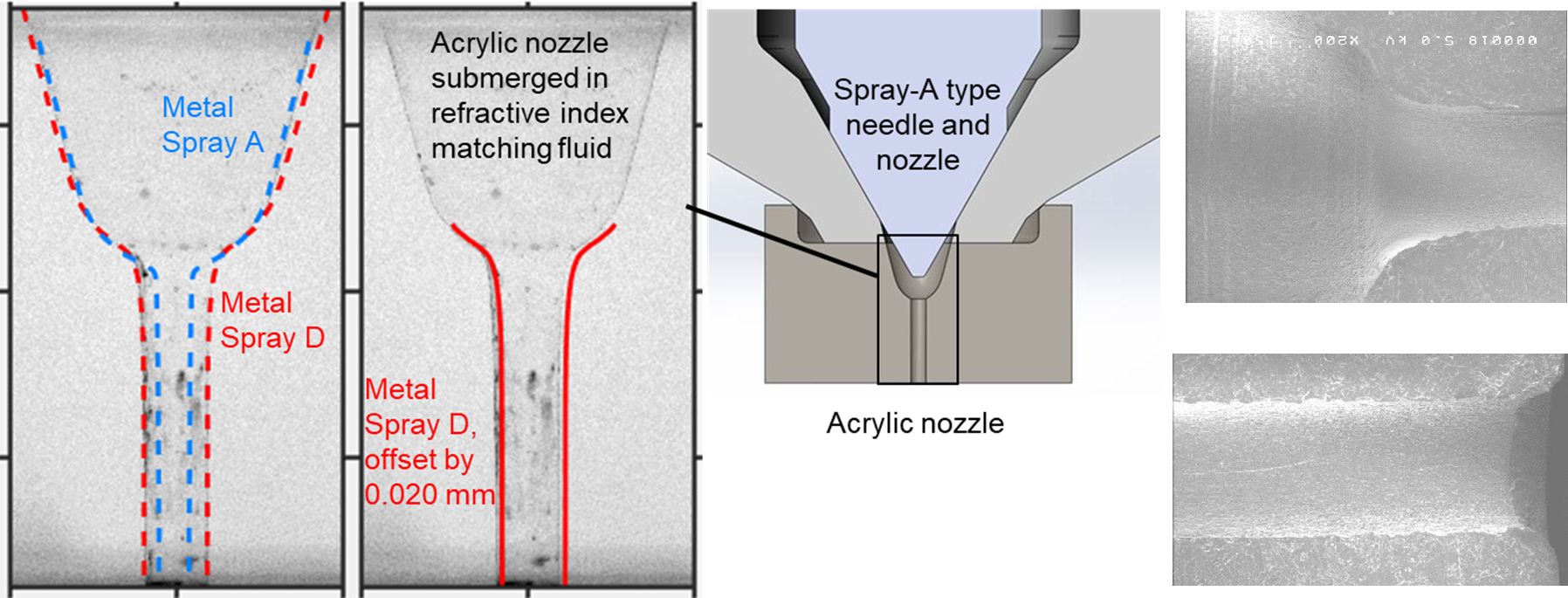
Figure 1 Left: (1) Optical microscopy images of nozzle geometry compared to metal nozzle shapes; (2) Target Spray D shape offset slightly to the right to facilitate comparison to the acrylic wall geometry. Middle: Schematic showing the acrylic tip replacing the metal nozzle mounted on a ground-flat Spray A injector. Right: Geometrical details showing machining marks and other features obtained via SEM imaging of a sectioned tip; the top image illustrates the sac and orifice entrance, while the bottom one shows the region near the orifice exit.
The transients of needle opening and closing are visualized with stereoscopic high-speed microscopy at injection pressures relevant to modern diesel engines, as illustrated below. The experiments show that a significant amount of gas may be present within the injector sac at the beginning of injection. Experiments were performed with different sac status, from almost completely empty to completely full. Video 1 presents two extreme examples, one with injection starting with the sac and orifice nearly full of gas (no liquid), and another with the sac and orifice full of liquid (no gas). The initial gas content strongly affects the shape and dispersion of the liquid at the beginning of injection. Gas may reside in the sac for a significant period of time after the beginning of injection.
Video 1 Sequences showing the start of injection with different sac status regarding the presence of gas. Top: 25 MPa into 0.1 MPa, sac and orifice full of gas; Bottom: 50 MPa into 0.1 MPa, nozzle full of liquid.
Reasons for different levels of gas initially within the injector sac are revealed by considering the needle closure at the end of injection. During the end of injection, the imaging shows widespread cavitation throughout the bulk of the sac. The cavitation bubbles collapse as pressure equilibrates within the sac, which ingests chamber gas into the sac and orifice.
Video 2 Sequences showing the end of injection processes at two chamber conditions. Top: 50 MPa into 2.0 MPa, no gas exchange is observed; Bottom: 50 MPa into 0.1 MPa, shows bulk cavitation and gas exchange.
Citation
J. Manin, L. M. Pickett, and K. Yasutomi. Stereoscopic high-speed microscopy to understand transient internal flow processes in high-pressure nozzles. Experimental Thermal and Fluid Science 114:110027, 2020